Online Calculator
Follow our step by step calculator to get your steel roofing quote direct from Cardinal Steels
Measuring Mono Pitch Roofs
Mono pitch roofs are common in garages and car ports. Sometimes, the roof width is more than the sheet length needed. The example here helps with measurements for the right roofing sheets.
Measuring mono pitch roofs is usually easy. You need a width measurement for sheet quantity and a length measurement for sheet length. If needed, use flashings at the ridge end and sides, and the type of flashing depends on the situation.
Measuring Apex Roofs
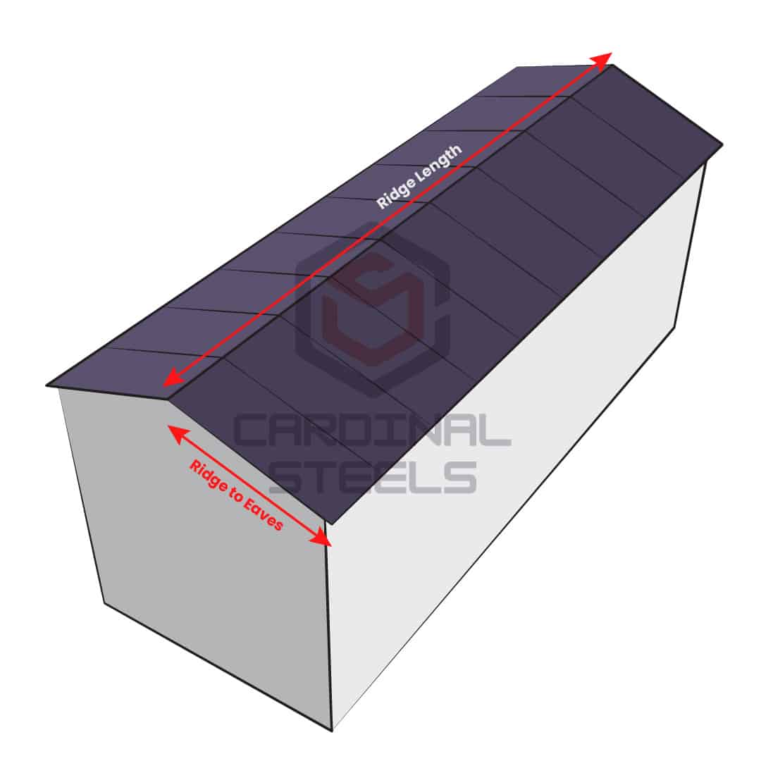
Apex roofs are typically symmetrical but can also be asymmetrical (with varying sheet lengths on each side). The provided diagram offers instructions for the necessary measurements to accurately specify your roofing sheets.
The ridge length is used to determine the number of sheets needed for each side, while the ridge to eaves measurement is used for calculating sheet lengths. In the case of an uneven apex, measurements from ridge to eaves must be taken on both sides.
Measuring Connected Apex Roofs
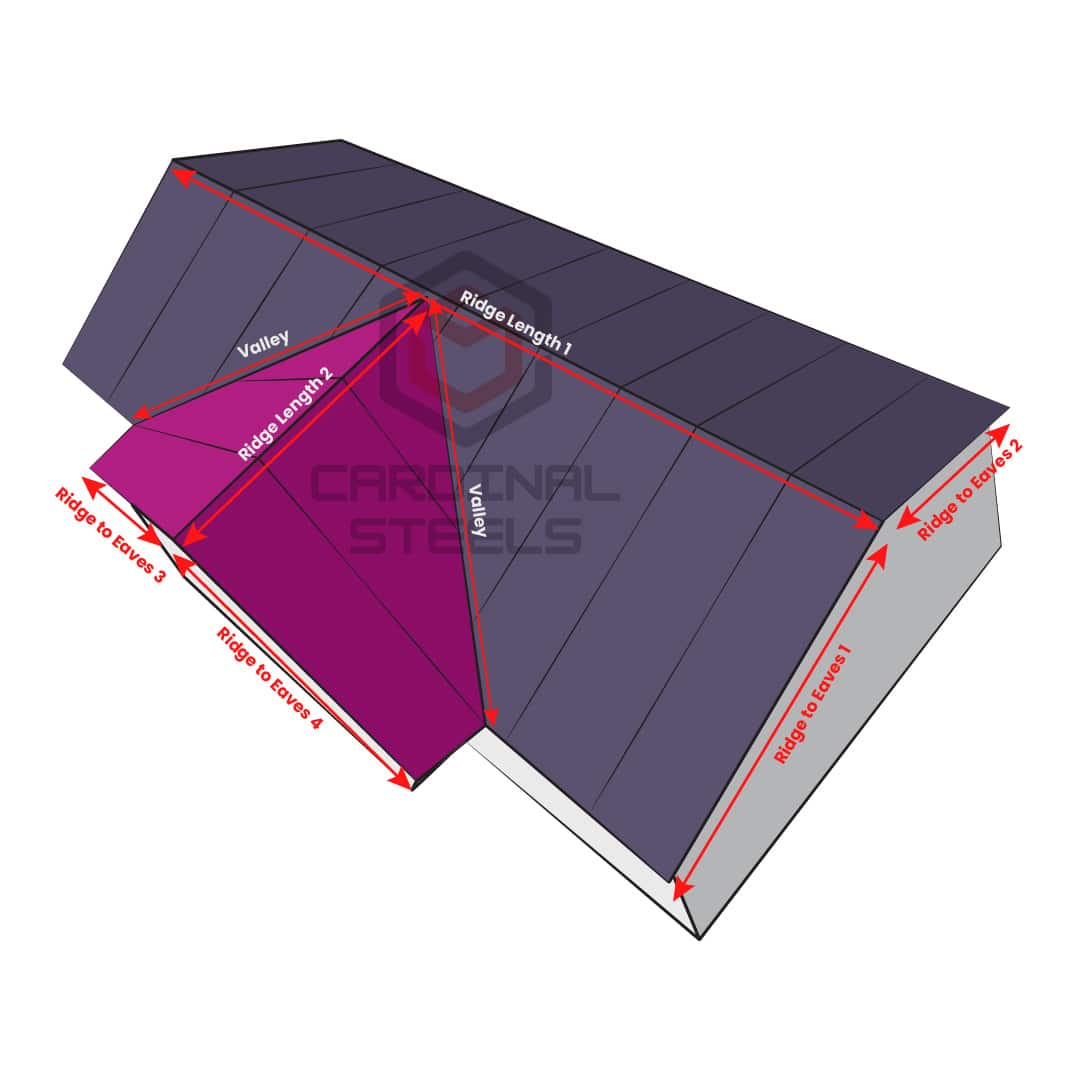
Connected apex roofs involve multiple apex roofs joined together. Measurements for these roofs should be taken with some variations compared to a standard apex roof. On-site cutting of sheets is necessary at the roof joints, and valley or hip flashing should be installed at these connections. The following examples provide instructions on the measurements required to accurately specify your roofing sheets.
Example 1 – T-Shaped Apex Roofs
This illustration represents a common type of connected apex roof, often referred to as T-shaped. The connections create two valleys that require flashing. Measurements are essentially taken for two separate roofs, as indicated above in blue and green.
To determine the necessary sheets for the primary apex, ridge line 1 is measured to calculate the required sheet quantity. Ridge to eaves measurements 1 and 2 are used to determine sheet lengths on each side of the apex.
The same process is then applied to apex 2 using ridge line 2, and ridge to eaves measurements 3 and 4.
On-site sheet cutting is performed to shape the valleys. It is recommended to use two-piece valley gutter flashings to redirect water and create a tidy finish where sheets meet at the valley. Ridge flashings are applied at the apex tips, and bargeboards can be used along the gable ends.
Example 2 – L-Shaped Apex Roofs
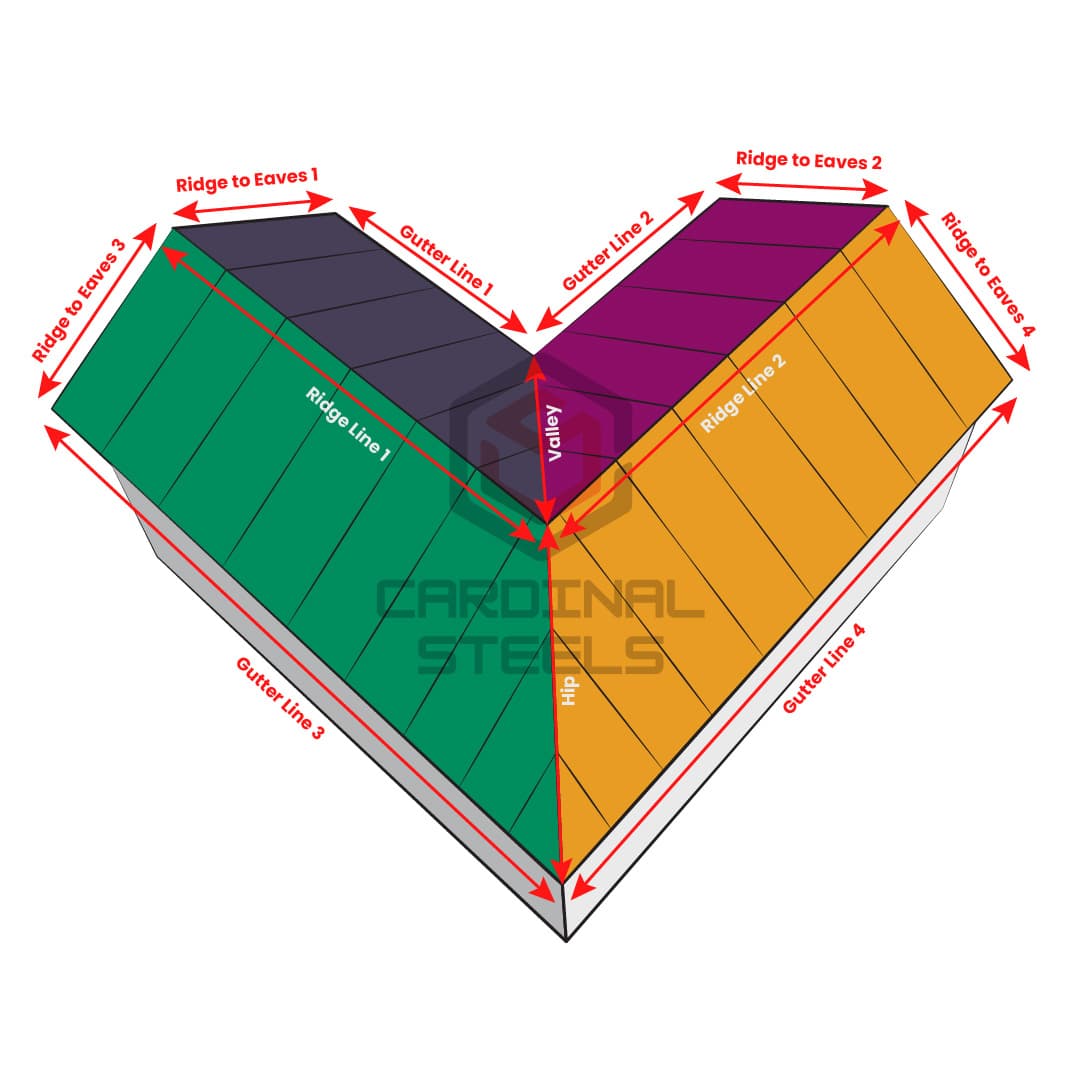
The provided example is somewhat more intricate than the T-shaped roof and should be essentially treated as four distinct areas.
To determine sheet requirements, measurements need to be taken along ridge line 1 and ridge to eaves 1. This process is then repeated for ridge line 2 and ridge to eaves 2, providing sheet size specifications for the inside section of the L-shaped roof.
Subsequently, measurements for the outside section should be taken from gutter line 3 and ridge to eaves 3, followed by gutter line 4 and ridge to eaves 4.
In this example, a valley is formed on the inside, and a hip is formed on the outside. Two-piece valley flashings and hip flashings are recommended where sheets meet at the valley and hip. Ridge flashings are applied at the ridge line (tip of the apex), and bargeboards can be used along the gable ends.
Measuring Hipped Roofs
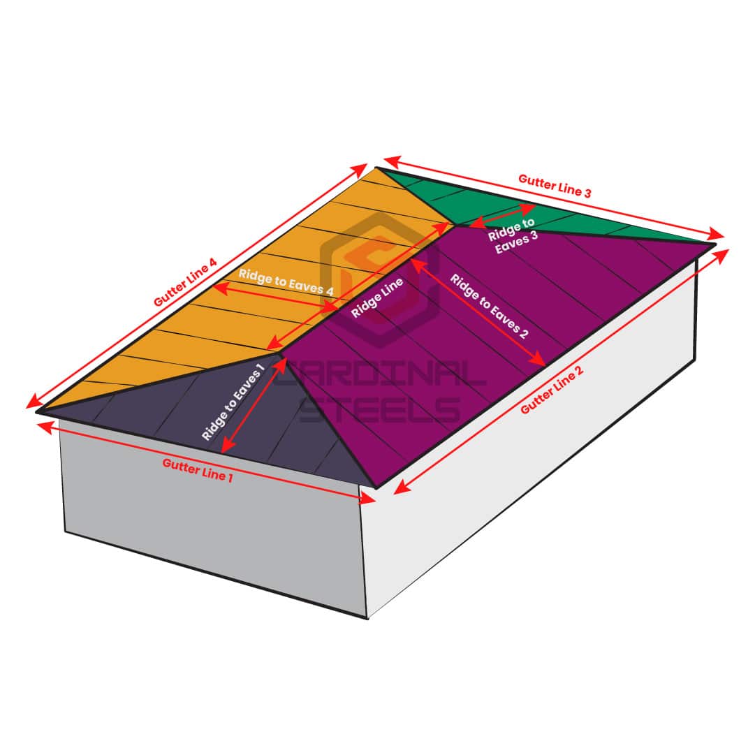
Gabled cladding is necessary for hipped roofs, covering both the gable ends and the two sides of the apex. This results in the need for cladding in four distinct areas.
Measurements for these roofs need to be approached differently compared to a standard apex roof. On-site sheet cutting is necessary at the meeting points of each cladded area, and hip flashing should be installed at these junctions. The diagram provides guidance on the measurements required for accurately specifying your roofing sheets.
Hipped roofs necessitate cladding in four distinct sections. Measurements are required along the gutter line and ridge to eaves for all four sections.
Use hip flashings at the junctions where sheets meet, with the quantity of hip flashing determined by measuring each individual hip join.
Ridge flashings are applied at the ridge line, which is the tip of the apex. The quantity of ridge flashing is determined by measuring the ridge line.


